Support for VSAT and TVRO systems
Troubleshooting
Troubleshooting Guide Maritime Antenna Systems
If your TVRO or VSAT system malfunctions, you will find an error message on the control unit display. Please observe the following notes for troubleshooting.
TVRO Antenna Systems
| Display | Problem | What to do |
Connection error |
The error message on the ACU display shows that there is currently no connection to the antenna or the antenna is powered off by the ACU. |
● Please recheck the cabling & connectors. Also make sure that the ACU is placed away from any external interference like Wifi router. |
FAN1 failure |
Back-side FAN in ACU failed. |
● check Fan1 speed under "ACU diagnostics" on web-page or ● check Fan1 speed directly on the ACU by clicking the right / left navigation buttons. |
FAN2 failure |
Board-side FAN in ACU failed. |
● check Fan2 speed under "ACU diagnostics" on web-page or ● check Fan1 speed directly on the ACU by clicking the right / left navigation buttons. |
ODU undervoltage |
ODU voltage is not optimal. |
● Check the RX cable and connector for damages. The ACU will automatically switch off the ODU. |
input undervoltage |
Drop in input voltage at ACU. |
● Check power supply and power cable connector to ACU. ● Check <Vin> in ACU Diagnostics for the current voltage value. |
ODU overcurrent |
Overcurrent in the ODU has been detected. |
● Check RX cable for short. |
Temp Alarm ODU |
ODU power supply unit in ACU overheated. | * |
Temp Alarm 12V |
12V regulator power supply unit in ACU overheated. | * |
Temp Alarm Airtemp |
The overall air-temperature inside the ACU is too high. (Warning) | * |
* If any of the temperature alarms go off frequently, then the user should investigate whether the ACU is installed with proper ventilation. Additionally check if the FANs in the ACU are failing. (Fan speeds are available in the diagnostics mode of the ACU display. If any of the FANs are failing, contact the support to fix the issue.)
* If a temperature alarm goes off, its respective module is turned automatically off, to save it from heat damage.
VSAT Antenna Systems
| Display | Problem | What to do |
Connection error |
The error message on the ACU display shows that there is currently no connection to the antenna or the antenna is powered off by the ACU. |
● Please recheck the cabling & connectors. Also make sure that the ACU is placed away from any external interference like Wifi router. |
FAN1 failure |
Back-side FAN in ACU failed. |
● check Fan1 speed under "ACU diagnostics" on web-page or ● check Fan1 speed directly on the ACU by clicking the right / left navigation buttons. |
FAN2 failure |
Board-side FAN in ACU failed. |
● check Fan2 speed under "ACU diagnostics" on web-page or ● check Fan2 speed directly on the ACU by clicking the right / left navigation buttons. |
ODU undervoltage |
ODU voltage is not optimal. |
● Check the RX cable and connector for damages. The ACU will automatically switch off the ODU. |
BUC undervoltage |
BUC is getting underpowered. |
● Check the TX cable and connector. The ACU will automatically switch off the BUC. |
input undervoltage |
Drop in input voltage at ACU. |
● Check power supply and power cable connector to ACU. ● Check <Vin> in ACU diagnostics for the current voltage value. |
ODU overcurrent |
Overcurrent in the ODU has been detected. |
● Check RX cable for short. |
BUC overcurrent |
Overcurrent in the BUC has been detected. |
● Check TX cable for short. |
Temp Alarm BUC1 |
The measured temperature for the BUC power supply unit in the ACU is too high. | * |
Temp Alarm BUC2 |
The measured temperature for the BUC power supply unit in the ACU is too high. | * |
Temp Alarm ODU |
ODU power supply unit in ACU overheated. | * |
Temp Alarm 12V |
12V regulator power supply unit in ACU overheated. | * |
Temp Alarm Airtemp |
The overall air-temperature inside the ACU is too high. (Warning) | * |
* If any of the temperature alarms go off frequently, then the user should investigate whether the ACU is installed with proper ventilation. Additionally check if the FANs in the ACU are failing. (Fan speeds are available in the diagnostics mode of the ACU display. If any of the FANs are failing, contact the support to fix the issue.)
* If a temperature alarm goes off, its respective module is turned automatically off, to save it from heat damage.
Status screen
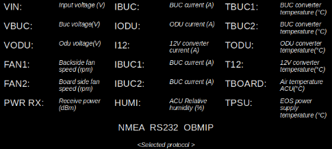 To display status screen / the ACU diagnostics report directly on the ACU, press on the right / left navigation buttons on the ACU front-panel, until you reach the System status screen as shown below. Alternatively, the real-time System diagnostics information is also available via the ACU web-interface. To do that, connect a computer to the ACU via LAN1 or LAN2. The default IP address is 192.168.1.254 or 192.168.2.254 respectively. Login with your provided username and password, and all the diagnostics information is available on the dashboard page.
Default screen / Main screen
 The default / main screen on the ACU looks like above. It shows the signal-to-noise ratio (dB) of the received signal. If the system is a VSAT system, then the main screen also shows the transmit status of the antenna, otherwise for a TV system, this block is empty. You can also view the satellite position and saved satellite name on the display screen. If any error occur in the ACU (as described in table above), then these are visible in the center block of the screen. The antennas current state (power-up, searching, optimize, connection error) is also seen on the default screen.
 LED-Status (VSAT-Systems)
Rx LED: It shows whether the antenna is locked to the satellite or not. If the LED is white, it means there is no connection to the antenna or the antenna is powered off. In this case, switch off the unit and recheck the RX cable and connector. A red led indicates error in communication with one of the modules of the ACU or that the display unit is not starting. Restart the ACU in this case, and if error persists, please contact the EPAK support team.
TX LED: It shows whether the antenna is transmitting or not. White LED indicates that the BUC is powered off. In this case, switch off the unit and recheck the TX cable and connector. A blue LED indicates that the BUC is powered on, but its not transmitting. This is not necessarily an error. The ACU switches off the transmit function, when the antenna is still searching for a signal or there could be complete / partial blockage to the satellite. A green LED shows that the BUC is powered on and transmitting. The user should have a internet connection in this case.
Status LED: If the LED is red, then there is a connection error to the antenna. In this case, check if the antenna is powered off or if there are any errors on the display. The LED is switched off in case there are no errors detected by the ACU.
LED-Status (TVRO-Systems)
RX LED: Same description as for VSAT
NET LED: This shows whether the TV system is connected to an internet source (either via the LTE or any external gateway). Blue indicates no internet connection to the system and green indicates its connected to the internet.
Status LED: Same description as for VSAT
TVRO AND VSAT EVO SYSTEMS (before 2020)
| Display | Problem | Solution |
no dish |
Control unit cannot communicate with E-Box. |
● Check antenna to control unit cable. ● Check antenna unit's power supply (12V ..36V) ● Test rotary joint for fault. |
Standby |
Antenna has no power OR antenna could not find satellite for 15 mins. |
● Check the error message seen before ("lowVsup" or "No dish") ● Recheck antenna's power supply |
ErrorCom |
Communication error with antenna unit. |
● Turn unit off and after 3 seconds on again |
LowVsup |
Power supply too low(< 11.5 Volt). |
● Check if power supply connection to antenna unit is too low (<11.5V) (loose cable..) or any voltage drop ● Check if voltage supply is continuous or it drops/varies sometimes ● Check for high resistance/load ● Check voltage on slip ring ● If there is sufficient voltage & low load, then the E-Box is faulty |
Err HR |
Read / Write error of horizontal unit. |
Turn the unit off and on again. In case the error reoccurs, call for technical assistance.
Err ULS / Err LLS: ● Check lose cable connection. |
Err VR |
Read / Write error of vertical unit. | |
Err SR |
Read / Write error of signal processing unit. | |
Err PR |
Read / Write error of polarisation unit. | |
Err VCO |
Error during satellite inspection. | |
Err EEP |
Error during storage. | |
Err IIC |
Error in internal communication. | |
Err Trck |
Error in tracking module. | |
Err ULS |
Error in upper / lower limit switch. | |
Err ELS |
Error in Eastern / Western Limit Switch | |
Err Save |
Error while saving satellite. |
● Repeat search and store. Make sure the boat is not moving and has no blockage. ● Try to save the satellite in different scan-bands ● If issue persists, after multiple retries, then replace E-Box |
Err Skew |
Cable connection from E-Box to Skew-Box may be defective. |
● Check the connection between E-Box and Skew-Box |
Wait GPS |
Antenna is waiting for valid GPS data OR Problem with GPS reception at current location. |
● GPS signal is jammed by another signal source ● GPS receiver is defective |
<Short!> |
There is a short circuit in the connection between control unit and antenna. |
● Check RX cable connection to antenna and rotary joint inside the antenna |
|
(TVRO Systems)
(VSAT Systems) |
No reception of the stored satellite. |
● Check if something obstructs the sight to the satellite ● Reception can be interrupted by passing boats |
scanning alternating withcomplete |
No receivable satellite signal in the entire search range OR LNB defective OR LNB cable is defective. |
● Check for line-of-sight issues ● Check, by using footprint cards (e.g. www.satbeams.com), whether the boat is inside the coverage area (footprint) ● Check antenna to control unit cable ● Check power to LNB ● Verify tracking frequencies |
update reco |
Saved satellite data is not completely similar to the real data measured by the antenna. |
● Update the stored satellite or delete and make new setup |
Blocked |
No reception of the stored satellite. |
● Check for line-of-sight issues |
No Data |
No frequency programmed. |
● Read the current frequencies via progsoft and verify if a valid frequency is present for the current scnband. If not, try to make a new setup with another scnband. ● Verify latest frequencies via lyngsat and reprogram antenna |